English
▼
Press ESC to close

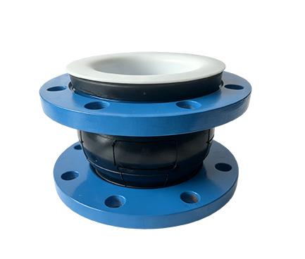
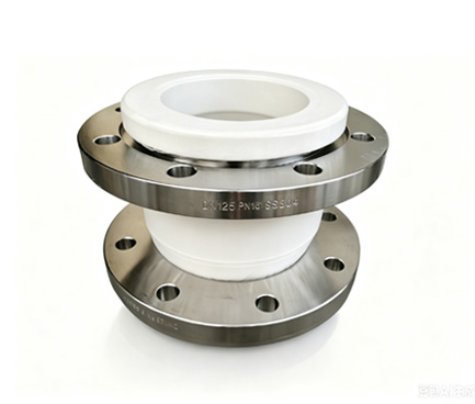
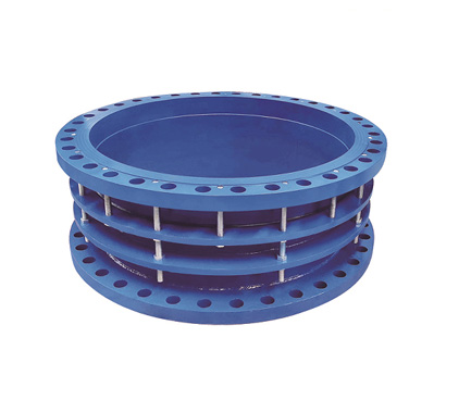
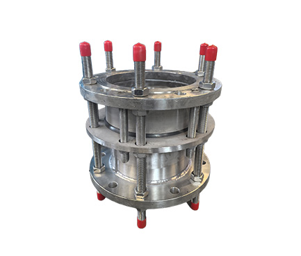
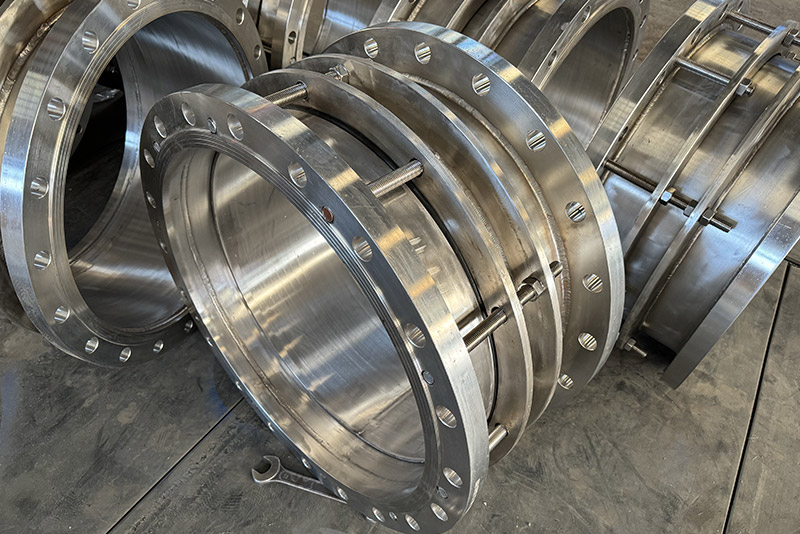
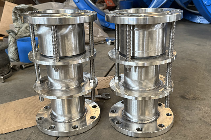
304/316L stainless steel double flange limit tie rod, corrosion-resistant, axial compensation, anti-pull-out, force transmission, specifically for chemical/municipal/pump room/sewage pipelines.
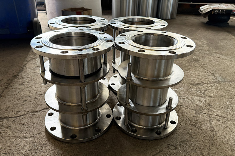
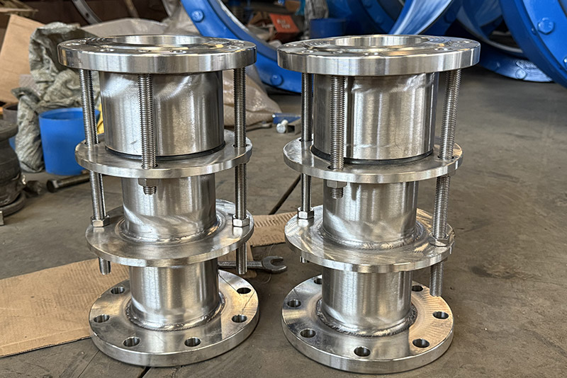
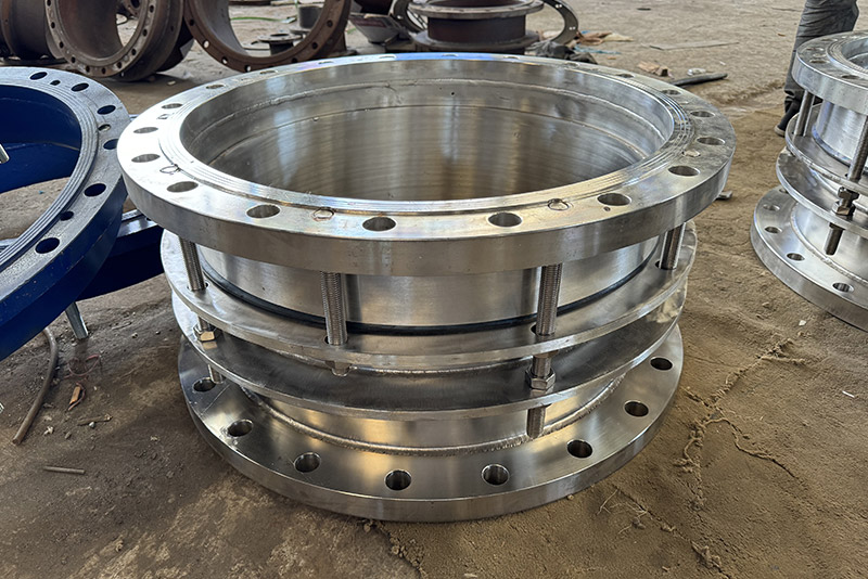
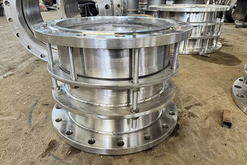
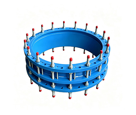
1. Body: 304/316L stainless steel, pressure-bearing, guiding.
2. Short Expansion Tube: Same material, sliding, compensates axial displacement.
3. Stainless Steel Flanges at Both Ends: Rotatable for bolt alignment, connects to pipes/valves.
4. Trapezoidal Rubber Sealing Ring: EPDM/NBR/fluororubber, self-tightening high-pressure seal.
5. Limit Tie Rod with Double Nuts: Stainless steel, controls expansion amount, prevents pull-out, transmits force.
Axial Compensation: Short tube slides during thermal expansion/contraction, absorbs ±20–±100mm displacement.
Limit Protection: Nuts lock when expansion exceeds limits, preventing pull-out and leakage.
Force Transmission and Load Reduction: Tie rods balance internal pressure on blind plates, protecting pumps and valves, simplifying supports.
Corrosion-Resistant Sealing: Stainless steel and specialty rubber, suitable for corrosive, sewage, and seawater applications.
1. Extremely Corrosion-Resistant: 304/316L does not rust, resistant to acids/bases/seawater/sewage, 15-year lifespan.
2. Large Compensation Range: Sufficient expansion stroke, suitable for long-distance pipelines/foundation settlement.
3. Flexible Installation: Flanges rotate to accommodate installation deviation and misaligned flanges.
4. Easy Maintenance: Adjustable limits and tight seals online, no need to cut pipes.
1. Chemical Pipelines: Acid-base, organic solvents, corrosive medium pipelines.
2. Municipal Sewage/Seawater: Sewage treatment plants, seawater desalination, coastal pipeline networks.
3. Pump Rooms/Valves: Water pump inlets and outlets, both ends of valves, prevents pull-out, provides force transmission protection.
4. Long-Distance/Overhead Pipelines: Sections with large thermal expansion or high settlement risk.
1. Flange Connection: Match flanges at both ends with pipeline flanges, evenly tighten bolts across diagonals.
2. Limit Adjustment: Pre-adjust nuts, reserve design expansion amount, leave space during operation.
3. Support Setting: Fix supports at both ends, balance internal pressure thrust.
4. Avoid Twisting: Install axially, avoid radial eccentric load.
| serial number | name | quantity | Material |
| 1 | Ontology | 1 | QT400-15、Q235A、ZG230-450、20 |
| 2 | sealing ring | 1 | NBR |
| 3 | Gland | 1 | QT400-15、Q235A、ZG230-450、20 |
| 4 | Limiting short pipe | 1 | Q235A、20、16Mn |
| 5 | long stud | n | Q235A、35、1Cr18Ni9Ti |
| 6 | nut | 4n | Q235A、20、1Cr18Ni9Ti |
| 7 | studs | n | Q235A、35、1Cr18Ni9Ti |
| Nominal diameter DN | Pipe outer diameter Dw | Overall dimensions | Amount of expansion △L |
Flange connection size | ||||||
| 0.6MPa | 1.0MPa | |||||||||
| L | L1 | D | D1 | n-do | D | D1 | n-do | |||
| 65 | 76 | 340 | 105 | 50 | 160 | 130 | 4-Φ14 | 185 | 145 | 4-Φ18 |
| 80 | 89 | 190 | 150 | 4-Φ18 | 200 | 160 | 8-Φ18 | |||
| 100 | 108 | 210 | 170 | 220 | 180 | |||||
| 114 | ||||||||||
| 125 | 133 | 340 | 105 | 50 | 240 | 200 | 8-Φ18 | 250 | 210 | 8-Φ18 |
| 140 | ||||||||||
| 150 | 159 | 265 | 225 | 8-Φ18 | 285 | 240 | 8-Φ22 | |||
| 168 | ||||||||||
| 200 | 219 | 320 | 280 | 340 | 295 | |||||
| 250 | 273 | 375 | 335 | 12-Φ18 | 395 | 350 | 12-Φ22 | |||
| 300 | 325 | 350 | 130 | 65 | 440 | 395 | 12-Φ22 | 445 | 400 | |
| 350 | 377 | 490 | 445 | 505 | 460 | 16-Φ22 | ||||
| 400 | 426 | 540 | 495 | 16-Φ22 | 565 | 515 | 16-Φ26 | |||
| 450 | 480 | 595 | 550 | 615 | 565 | 20-Φ26 | ||||
| 500 | 530 | 645 | 600 | 20-Φ22 | 670 | 620 | ||||
| 600 | 630 | 755 | 705 | 20-Φ26 | 780 | 725 | 20-Φ30 | |||
| 700 | 720 | 860 | 810 | 24-Φ26 | 895 | 840 | 24-Φ30 | |||
| 800 | 820 | 590 | 220 | 130 | 975 | 920 | 24-Φ30 | 1015 | 950 | 24-Φ33 |
| 900 | 920 | 1075 | 1020 | 1115 | 1050 | 28-Φ33 | ||||
| 1000 | 1020 | 1175 | 1120 | 28-Φ30 | 1230 | 1160 | 28-Φ36 | |||
| 1200 | 1220 | 1405 | 1340 | 32-Φ33 | 1455 | 1380 | 32-Φ40 | |||
| 1400 | 1420 | 1630 | 1560 | 36-Φ36 | 1675 | 1590 | 36-Φ42 | |||
| 1500 | 1520 | 1730 | 1660 | |||||||
| 1600 | 1620 | 1830 | 1760 | 40-Φ36 | 1915 | 1820 | 40-Φ48 | |||
| 1800 | 1820 | 2045 | 1970 | 44-Φ40 | 2115 | 2020 | 44-Φ48 | |||
| 2000 | 2020 | 2265 | 2180 | 48-Φ42 | 2325 | 2230 | 48-Φ48 | |||
| 2200 | 2220 | 2475 | 2390 | 52-Φ42 | 2550 | 2440 | 52-Φ56 | |||
| 2400 | 2420 | 2685 | 2600 | 56-Φ42 | 2760 | 2650 | 56-Φ56 | |||
| 2600 | 2620 | 600 | 240 | 140 | 2905 | 2810 | 60-Φ48 | 2960 | 2850 | 60-Φ56 |
| 2800 | 2820 | 3115 | 3020 | 64-Φ48 | 3180 | 3070 | 64-Φ56 | |||
| 3000 | 3020 | 3315 | 3220 | 68-Φ48 | 3405 | 3290 | 68-Φ60 | |||
| Note: This dimension conforms to GB/T12465-2002 standard. | ||||||||||
| Instructions: This product is suitable for connections to flanges on both ends. During installation, adjust the length of the connections at both ends, tighten the gland bolts diagonally and evenly, and then adjust the limit nuts. This allows the pipeline to expand and contract freely, locking the amount of expansion and contraction to ensure safe pipeline operation. Production range: DN32-4000. | ||||||||||